GMVC96 Installation Manual: A Comprehensive Plan
This manual provides detailed instructions for the safe and efficient installation of the GMVC96 furnace.
It covers crucial aspects, from unpacking and safety precautions to electrical connections and venting system setup.
Ensure proper installation for optimal performance and longevity, referencing diagrams and adhering to local codes.
The GMVC96 is a high-efficiency, 96% Annual Fuel Utilization Efficiency (AFUE) gas furnace designed to provide reliable and comfortable heating for your home. This furnace utilizes a modulating gas valve and a variable-speed blower motor to deliver consistent temperatures and quiet operation. It’s engineered for optimal performance and energy savings, reducing heating costs while maintaining a comfortable indoor environment.
This furnace model incorporates advanced features such as a sealed combustion system, which enhances safety and efficiency by drawing combustion air directly from outside. The GMVC96 is also designed for easy maintenance, with readily accessible components for filter replacement and routine inspections. Proper installation is paramount to realizing the full benefits of this furnace.
Before beginning the installation process, carefully review this manual and familiarize yourself with all safety precautions and procedures. Ensure you have the necessary tools and materials, and that the installation site meets the specified clearance requirements. Referencing the provided wiring diagrams and following the step-by-step instructions will ensure a successful and safe installation. The GMVC96 is a significant investment, and proper installation is key to its long-term performance and reliability.
Safety Precautions
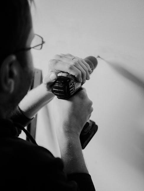
Prior to commencing any installation or maintenance work on the GMVC96 furnace, disconnect the electrical power supply at the breaker panel. Failure to do so presents a serious risk of electrical shock. Always verify the power is off with a reliable testing device. Gas supply must also be shut off at the gas valve before making any connections or disconnections to the gas line.
Carbon monoxide is a deadly gas. Ensure proper venting is established and maintained to prevent carbon monoxide buildup. Never operate the furnace without a properly connected vent system. Wear appropriate personal protective equipment (PPE), including safety glasses, gloves, and work boots, throughout the installation process.
Be cautious when handling sharp objects and tools. Avoid contact with hot surfaces during and after operation. Do not modify or alter the furnace in any way without explicit authorization from the manufacturer. Improper modifications can compromise safety and void the warranty. Always follow local codes and regulations regarding furnace installation and venting. If you are not qualified to perform this installation, contact a licensed HVAC professional. Keep flammable materials away from the furnace.
Unpacking and Inspection
Upon delivery of the GMVC96 furnace, carefully inspect the shipping container for any signs of damage during transit. Note any visible dents, punctures, or crushing on the shipping documentation before accepting the delivery. Do not accept a damaged shipment without documenting the damage with the carrier.
Once the unit is delivered, carefully unpack the furnace, ensuring all packing materials are removed. Compare the contents against the packing list to verify all components are present. This includes the furnace itself, vent pipes, control board, wiring harnesses, and any included accessories.
Thoroughly inspect the furnace for any signs of shipping damage, such as bent fins, loose panels, or damaged wiring. Report any discrepancies or damage to your supplier immediately. Retain all packaging materials until the inspection is complete and you are satisfied with the condition of the unit. Do not attempt to operate a damaged furnace. Document any findings with photographs for potential warranty claims. Ensure the unit’s serial number matches the documentation.
Tools and Materials Required

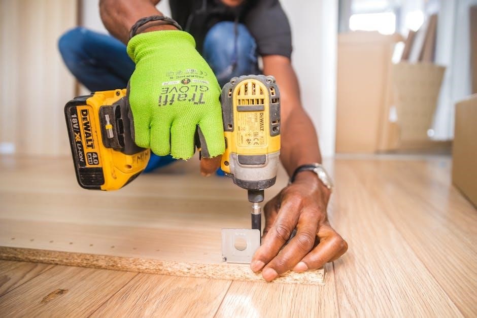
Successful GMVC96 furnace installation necessitates a comprehensive toolkit and appropriate materials. Essential tools include a refrigerant recovery machine (EPA certified technician required), vacuum pump, manifold gauge set, and combustion analyzer. Standard hand tools such as screwdrivers (various types), wrenches (adjustable and fixed size), pliers, wire strippers, and a multimeter are also crucial.
Additional requirements encompass a pipe cutter, flaring tool (for gas line connections), level, drill with various bits, and a hole saw for vent pipe installation. Safety equipment is paramount; always wear safety glasses, gloves, and appropriate work boots.
Necessary materials include appropriately sized gas piping (black iron or approved flexible gas line), vent pipe (specified by local codes and furnace requirements), electrical wiring (correct gauge for the circuit), condensate drain tubing (PVC or approved material), and sealant/tape for connections. Ensure you have sufficient solder, flux, and fittings for gas line connections. Confirm compatibility of thermostat wiring with the GMVC96 control board. Always adhere to local building codes and manufacturer specifications.
Furnace Location and Clearance Requirements
Proper furnace placement is critical for safe and efficient operation of the GMVC96. Select a location that provides adequate clearance for servicing, airflow, and complies with local building codes. Avoid areas prone to moisture, combustible materials, or obstructions hindering access.
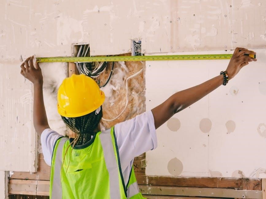
Minimum clearances are essential. Maintain at least 6 inches of clearance on all sides – top, bottom, front, and rear – unless otherwise specified in the installation manual. Specific attention should be given to the vent termination point, ensuring it meets code requirements for proximity to windows, doors, and other structures.
Consider the floor’s structural integrity; the GMVC96 is a substantial unit and requires a level, stable surface. Ensure sufficient combustion air is available, particularly in confined spaces. Follow guidelines regarding proximity to gas lines and electrical panels. Verify adequate space for condensate drain installation and access for future maintenance. Always consult local codes and the GMVC96 installation manual for precise clearance specifications.
Installing the Furnace – Step-by-Step Guide
Begin by carefully positioning the GMVC96 furnace on the prepared location, ensuring it’s level. Connect the condensate drain, verifying a proper slope for efficient drainage. Proceed with the gas line connection, utilizing approved piping and fittings, and rigorously leak-testing all connections. Next, establish the electrical connections, strictly adhering to the wiring diagram and local electrical codes.
Install the venting system, ensuring proper pitch and secure connections to prevent carbon monoxide leakage. Double-check all connections – gas, electrical, and venting – before proceeding. Mount the access panels securely, and prepare for initial startup. Verify the correct voltage and gas supply are available.
Before powering on, inspect all wiring and connections one last time. Follow the startup checklist meticulously, monitoring for any unusual noises or smells. Confirm proper operation of the blower motor and burner assembly. Document all installation details for future reference and warranty purposes. Refer to the complete installation manual for detailed diagrams and troubleshooting tips.
Gas Line Connection
Prior to commencing any gas line connection, ensure the gas supply is completely shut off at the main valve. Utilize only approved gas piping materials, such as black iron or corrugated stainless steel tubing (CSST), adhering to local codes and regulations. Apply a pipe joint compound specifically designed for gas lines to all threaded connections, avoiding any interference with gas flow.
Connect the gas supply line to the furnace’s gas control valve, ensuring a tight and leak-free seal. Employ a sediment trap (drip leg) upstream of the gas control valve to prevent debris from entering the system. After making all connections, conduct a thorough leak test using a soap and water solution. Apply the solution to all joints and fittings, observing for bubbles indicating a leak.
If leaks are detected, immediately shut off the gas supply and retighten the connections. Repeat the leak test until no leaks are present. Never use an open flame to check for gas leaks. Proper gas line connection is critical for safe and efficient furnace operation. Consult a qualified gas technician if you are unsure about any aspect of this process.
Electrical Connections – Wiring Diagram
Before initiating any electrical connections, completely disconnect power to the circuit at the breaker panel. Verify the power is off using a non-contact voltage tester. Refer to the detailed wiring diagram located on the furnace’s internal panel and within this manual for accurate connection guidance. Utilize appropriately sized wiring, adhering to local electrical codes and the furnace’s specifications.
Connect the ground wire to the designated grounding terminal on the furnace chassis. Connect the 120V power supply wires to the corresponding terminals, observing proper polarity. Connect the thermostat wiring according to the wiring diagram, ensuring correct identification of each wire (R, W, G, Y, C). Use wire connectors approved for electrical connections, securing them tightly.
Double-check all connections against the wiring diagram before restoring power. Ensure no bare wires are exposed. A properly wired furnace is essential for safe and reliable operation. If you are unfamiliar with electrical wiring, consult a qualified electrician. Incorrect wiring can cause damage to the furnace or create a safety hazard.
Venting System Installation
Proper venting is critical for safe and efficient furnace operation, removing combustion gases. Utilize only venting components specifically approved for use with 96% AFUE furnaces, such as PVC or CPVC. Consult local codes for venting requirements, as they vary by location. Ensure the vent pipe maintains a consistent upward slope, preventing condensate from pooling.
Carefully measure and cut the vent pipe to the required lengths, using a PVC/CPVC cutter. Securely join all vent pipe sections using approved PVC/CPVC cement and fittings. Seal all joints thoroughly to prevent leaks. The vent termination must be located according to manufacturer’s instructions and local codes, ensuring adequate clearance from windows, doors, and other openings.
Inspect the entire venting system for proper slope, secure connections, and correct termination. Avoid sharp bends or restrictions in the vent pipe. A compromised venting system can lead to carbon monoxide buildup, posing a serious safety risk. Regularly inspect the venting system for damage or deterioration.
Condensate Drain Installation
High-efficiency furnaces, like the GMVC96, produce condensate as a byproduct of combustion. Proper condensate drainage is essential to prevent water damage and ensure efficient operation. Install a condensate drain line using ¾” PVC pipe, sloping continuously downward from the furnace to a suitable drain.
Connect the drain line to a floor drain, standpipe, or other approved drainage point. Avoid direct connection to the sewer system without an air gap, preventing potential backflow. A trap should be installed in the drain line to prevent sewer gases from entering the furnace. Ensure the trap is accessible for cleaning and maintenance.
Insulate the condensate drain line to prevent freezing in cold climates. Regularly inspect the drain line for clogs or leaks. A clogged drain line can cause the furnace to shut down. Consider installing a condensate pump if gravity drainage is not possible. Verify proper drainage after installation by pouring water into the condensate pan.
Thermostat Compatibility and Wiring
The GMVC96 furnace is compatible with a wide range of thermostats, including both mechanical and digital models. However, for optimal performance and access to advanced features, a programmable thermostat is recommended. Ensure the thermostat is compatible with the furnace’s control voltage (typically 24VAC).
Refer to the wiring diagram located on the furnace’s control board and in this manual for specific wiring instructions. Common thermostat wires include R (power), C (common), W (heat), Y (cool), and G (fan). Properly identify each wire before connecting it to the thermostat terminals. Incorrect wiring can damage the furnace or thermostat.
If replacing an existing thermostat, label the wires before disconnecting them. Use wire nuts to securely connect the wires to the thermostat terminals. Double-check all connections before restoring power. Some advanced thermostats may require additional configuration or programming. Consult the thermostat’s manual for detailed instructions.
Control Board Overview and Functions
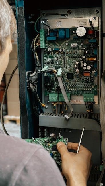
The GMVC96 furnace’s control board is the central nervous system, managing all operational functions. It receives input from various sensors and the thermostat, then controls the ignition system, blower motor, and gas valve. Key components include terminal blocks for wiring connections, LED indicators for status updates, and a diagnostic jumper for troubleshooting.
The control board’s primary functions encompass monitoring safety sensors (flame sensor, high-limit switch), sequencing the heating cycle, and responding to thermostat commands. It also manages condensate pump operation and provides error code diagnostics. Understanding the LED indicators is crucial; a flashing light typically signifies an error condition, requiring further investigation.
The board features terminals for connecting the thermostat, gas valve, induced draft motor, and other essential components. Always refer to the wiring diagram for correct connections. Caution: Disconnect power before accessing or working on the control board. Improper handling can lead to electrical shock or damage to the system. Regular inspection of the board for any signs of damage is recommended.
Initial Startup and Checklist
Before initiating the GMVC96 furnace, a thorough pre-startup checklist is essential. Verify all gas line connections are leak-free using a soap solution, and confirm proper venting installation. Ensure the electrical connections match the wiring diagram and that the furnace is correctly grounded. Check the condensate drain line for obstructions and proper flow.
Upon powering up, observe the control board for any immediate error codes. Set the thermostat to heat mode and initiate a heating cycle. Monitor the ignition sequence, flame presence, and blower operation. Listen for any unusual noises or smells. Confirm the furnace reaches the setpoint temperature and cycles off correctly.
The checklist includes: Gas pressure verification, airflow measurement, and combustion analysis. Record these readings for future reference. Inspect all connections again after a short operational period. Educate the homeowner on proper thermostat operation and filter replacement procedures. Document the startup date and any observed issues for warranty purposes. A successful startup ensures safe and efficient operation.
Troubleshooting Common Issues
Common GMVC96 furnace issues often stem from simple causes. No heat can indicate a tripped circuit breaker, a faulty thermostat, or a blocked vent. Flame rollout suggests a dirty flame sensor, improper gas pressure, or a cracked heat exchanger – requiring immediate attention. Blower motor failure may be due to a capacitor issue or a worn-out motor.
Error codes (see section ‘Understanding Error Codes’) provide valuable diagnostic clues. Condensate drain clogs cause water damage and shutdown; regular cleaning is vital. Gas valve problems can result in no gas flow or inconsistent heating. Electrical connection issues manifest as intermittent operation or complete failure.
Troubleshooting steps include: Checking the thermostat batteries, resetting the furnace, cleaning the flame sensor, and inspecting the air filter. Always disconnect power before performing any maintenance. If unsure, consult a qualified HVAC technician. Regular maintenance prevents many issues. Ignoring problems can lead to costly repairs and safety hazards. Prioritize safety and follow all instructions carefully.
Understanding Error Codes
The GMVC96 furnace utilizes a diagnostic system displaying error codes to pinpoint malfunctions. Code 121 typically indicates a flame rollout issue, potentially caused by a dirty flame sensor or a cracked heat exchanger – requiring professional inspection. Code 120 signals a loss of flame, often due to gas supply problems or a faulty igniter. Code 32 suggests an over-temperature limit switch tripped, indicating airflow restriction or overheating.

Code 15 points to a flame detection problem, possibly a dirty flame sensor or weak flame. Code 94 indicates a condensate overflow, necessitating drain line clearing. Code 50 signals a low gas pressure issue, requiring gas valve inspection. Code 11 suggests an open high limit switch, indicating a potential overheating issue.
Refer to the complete error code list in the appendix for a comprehensive understanding. Do not attempt repairs based solely on error codes; always verify the issue with a thorough inspection. Some codes require professional diagnosis and repair. Resetting the furnace after addressing the issue may clear the code. Documenting error codes aids technicians in efficient troubleshooting.
Maintenance Schedule
Regular maintenance is crucial for optimal GMVC96 furnace performance and longevity. Annually, schedule a professional inspection encompassing burner cleaning, heat exchanger evaluation, and safety control checks. Monthly, inspect and replace the air filter – a clogged filter restricts airflow, reducing efficiency and potentially causing overheating. Every six months, visually inspect the venting system for obstructions or damage, ensuring proper exhaust flow.
Inspect the condensate drain line quarterly, clearing any blockages to prevent water damage. Periodically check gas connections for leaks using a soap solution – never use a flame. Clean the blower assembly annually to maintain efficient airflow. Lubricate motor bearings as needed, following manufacturer’s recommendations.
Keep the furnace area clear of debris and combustible materials. Document all maintenance activities for warranty purposes. Consider a service contract for proactive maintenance and priority repairs. Following this schedule maximizes efficiency, minimizes breakdowns, and extends the life of your GMVC96 furnace. Ignoring maintenance can lead to costly repairs and reduced performance.
Filter Replacement Instructions
Regular filter replacement is vital for maintaining optimal GMVC96 furnace performance and indoor air quality. Always turn off the furnace power at the breaker box before beginning. Locate the filter access panel, typically on the furnace’s return air duct. Remove the access panel, often secured with latches or screws.
Note the filter’s size and airflow direction indicated by an arrow on the filter frame. Carefully remove the old filter, noting any accumulated dust or debris. Clean the filter access area to prevent dust from entering the furnace. Insert the new filter, ensuring the airflow arrow points in the correct direction – towards the blower.
Replace the filter access panel, securing it properly. Restore power to the furnace at the breaker box. Check for proper airflow after restarting the system. Replace filters monthly during peak usage seasons and every three months otherwise. Using the correct filter size is crucial for efficient operation. Dispose of used filters responsibly.
Cleaning Procedures
Regular cleaning extends the lifespan and maintains the efficiency of your GMVC96 furnace. Always disconnect power to the unit at the breaker box before any cleaning procedure. Begin by visually inspecting the furnace for dust and debris accumulation. Use a vacuum cleaner with a brush attachment to gently remove dust from the blower compartment, burner assembly, and heat exchanger.
Avoid using harsh chemicals or abrasive cleaners, as they can damage components. Clean the burner assembly carefully, ensuring all ports are clear of obstructions. Inspect the condensate drain line for clogs and flush with a mild solution of water and vinegar. Wipe down the exterior surfaces with a damp cloth.
Check and clean the flame sensor with fine steel wool if necessary. Ensure all components are completely dry before restoring power. Annual professional cleaning is recommended for a thorough inspection and maintenance. Cleaning the blower motor should be performed by a qualified technician. Proper ventilation is important during cleaning.
Goodman Furnace Efficiency Ratings (96%)
The GMVC96 furnace boasts a 96% Annual Fuel Utilization Efficiency (AFUE) rating, signifying exceptional energy savings. This high efficiency translates to lower heating bills and a reduced carbon footprint. AFUE measures how efficiently the furnace converts fuel into usable heat, with higher numbers indicating greater efficiency. A 96% AFUE means that 96% of the fuel consumed is converted into heating, while only 4% is lost during the combustion process.
This furnace’s efficiency is achieved through a sealed combustion system and a modulating gas valve. The sealed combustion draws air directly from outside, eliminating drafts and improving safety. The modulating gas valve adjusts the burner’s firing rate to match the heating demand, optimizing performance. Compared to older furnaces with lower AFUE ratings, the GMVC96 offers substantial cost savings over its lifespan.
Proper installation and maintenance are crucial to maintaining this high efficiency. Regular filter replacements and annual professional inspections ensure optimal performance. The 96% AFUE rating qualifies the GMVC96 for potential rebates and tax credits, further enhancing its value.